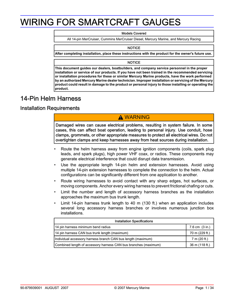
Smartcraft Gauge Wiring Diagram

If no data is received switch the wire connections around.
Smartcraft gauge wiring diagram. Smartcraft depth transducer wiring connections page 2 5 90 8m0063595 december 2011 2. 3d deals with the integration of nmea 2000 devices into the smartcraft network. A wire retainer b wire terminal c connector d assembled components e transducer connector. Architectural drawings and wiring pinouts are included in this section.
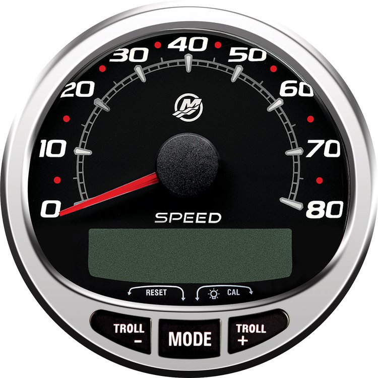
Locate the white and blue wires coming from the smartcraft speedometer har ness see wiring diagram. Smartcraft gauge test specifications. First look at the gps wiring diagram and determine what two leads are the gps output leads. Mercury smartcraft wiring diagrams wiring diagram is a simplified within acceptable limits pictorial representation of an electrical circuit it shows the components of the circuit as simplified shapes and the capacity and signal links in the company of the devices.
Push each wire terminal into its respective position in the wire retainer until they snap in place. The skyhook digital anchoring system holds your boat in a fixed position regardless of wind or current active trim is the only auto trimming program that uses gps and speed smartcraft dts digital throttle shift delivers precise and smooth handling with instant response and total control. Select a location and drill a 19 mm 0 750 in mounting hole. Smartcraft system tachometer and speedometer installation 90 898283006 september 2007 page 5 6 smart tow speedometer with gps wiring outside air temperature sensor installation 1.
Please read about the smartcraft system to get the best per formance from them. Architectural drawings and wiring pinouts are included in this section. Carefully draw the cord end of the data cable puller through the hull pulling the 14 pin helm harness through the vessel. Wiring for smartcraft gauges 90 879939001 august 2007 page 3 34 6.
Connect the gps output leads to the white and blue wires from the speedometer harness. Mercury s patented joystick piloting system delivers 360 degree directional control. Section 3b covers 14 pin smartcraft rigging. Inspect the harness insulation for any damage.
If your builder or dealer uses genuine mercury gauges and controls when installing the new engine on your boat the warranty coverage for those rigging components now matches the total warranty of your engine. Carefully inspect all connector pins seals and connector locking components for damage. If yes is selected then lighting levels made on this sc tach find great deals on ebay for mercury smartcraft wiring harness. Assemble the wire retainer securely into the connector.
Part 1 monitor 1 01 1 02 part 2 part 3 part 4 monitor 2 00 system tach speed smart tach speed 1 product identification for boats equipped with smartcraft gauge systems look to the descriptions below to identify the system in the boat. Mount the sensor where it will be exposed to outside air and not exposed to direct sunlight. To be properly selected port and stbd using a mercury engine diagnostic tool.


