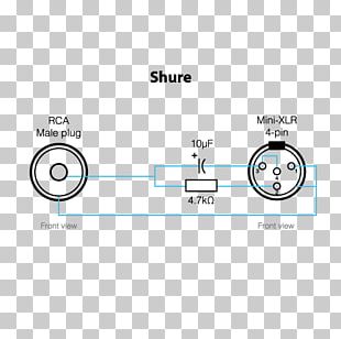
Shure 4 Pin Mini Xlr Wiring Diagram

Wiring Configuration For A Hsp 4 To A Shure Ta4f Connector

34090ee Shure 4 Pin Mini Xlr Wiring Diagram Wiring Resources

Xg 5518 Mini Xlr Wiring Diagram Download Diagram
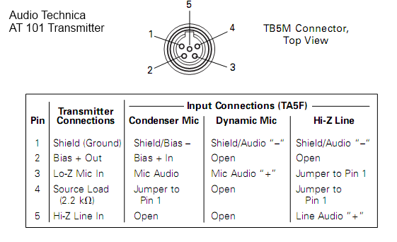
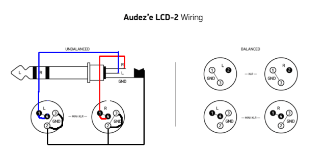
Convert From Ta4f To Ta5f Mini Xlr At Dvinfo Net
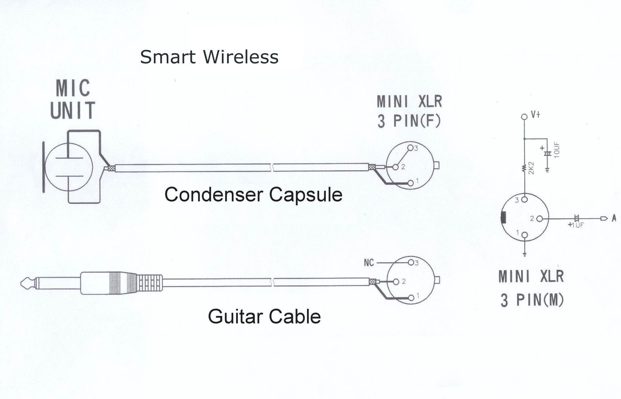
Wireless Microphone Schematics Point Source Audio

Mx391 User Guide

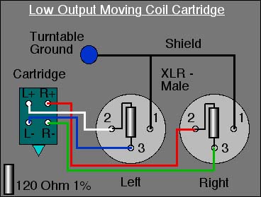
3 pin xlr microphone wiring diagram.
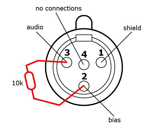
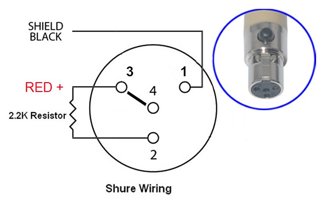
Shure 4 pin mini xlr wiring diagram. The following is the aes industry standard for balanced audio xlr wiring commonly known as pin 2 hot. Sleeve s b tip r use w3 type headset diagram. Pin 4 s pin 1 b pin 3 r 10k ohms 1 to 4 diagram. Bridging 1 4 for signal 2 3 for ground 2.
See wiring diagrams for compatibility with wireless brands. The three terminal 1 4 connector is commonly referred to as the trs or tip ring sleeve version. The following xlr 4 pin wiring diagram photo have been authored. My amp s balanced headphone jack has a 4 pin xlr but the diagram for the balanced cable shows a 3 pin xlr.
What s the correct wiring for 4 pin xlr termination. Mx 3 pin 4 pin 5 pin mini xlr type connector is a type of connector used for many professional audio applications. The ts connector is an unbalanced connector. Shure 4 pin mini connector.
Instrument cable connects a 1 4 jack to a 4 pin mini connector for bodypack transmitters. Is it correct that for the headphone end of the cable the mini xlr it s wired the same way for balanced or single ended. 3 5mm stereo locking plug. Mx xlr adapters do not suffer from insertion loss and high frequency cutoff.
Xlr 14 wiring connect the xlrs pin 1 to the xlr ground lug and to the 14 ground connect the xlrs pin 3 to the 14 tip. Sleeve s b tip r diagram. Xlr to ts 1 4 connecting a balanced xlr connector to. Xlr to 14 trs connector wired for balanced mono the usual way to connect a 3 pin xlr to a 14 trs aka stereo jack plug is to use the following pin allocation.
The trs connector can be used for many things including balanced audio send return for insert points and left right stereo just to name a few. Sleeve s tip w 2 7k ohms t to s diagram. Sleeve s b tip r diagram. On the four pin amphenol pin 2 is a high impedance unbalanced output.
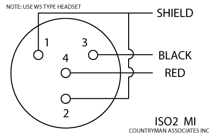
Pin 4 s pin 1 b pin 3 r 10k ohms 1 to 4 use w5 type headset diagram. Subscribe my channel http bit ly subscribe didiktv.

Ls 8024 Mini Xlr Wiring Diagram Wiring Diagram

Shure 4 Pin Mini Xlr Wiring Diagram Wiring Diagram
Wrg 1757 Xlr Microphone Cable Wiring Polarity Tester Sc
Shure Microphone 4 Pin Microphone Wiring Diagram Wiring Diagram
Monoprice M1570 Balanced Cable Guide Xlr Cable Zadiustech

Xy 0705 3 Pin Xlr Wiring Download Diagram
Wiring Diagram Rs 485 Rs 422 Pinout Png 800x714px Diagram Area

Mini Xlr Wiring Diagram Wiring Diagram
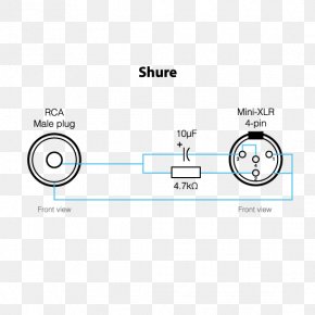
Xlr 4 High Quality Ta4f 4pin Mini Xlr4 To 3pin Male Xlr 48v

Ta4 Connector Question Gearslutz

Ulx User Guide
3 Pin Xlr Wiring Diagram Cable Wiring Etc

Xlr Microphone Wiring Diagram Shure Diagram Source