Copeland Current Relay Wiring

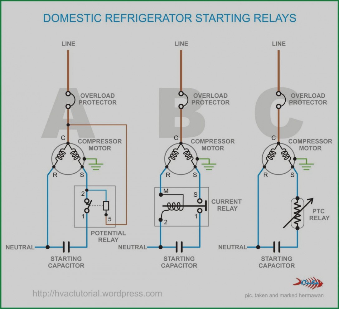
Know Your Potential Starting Relays

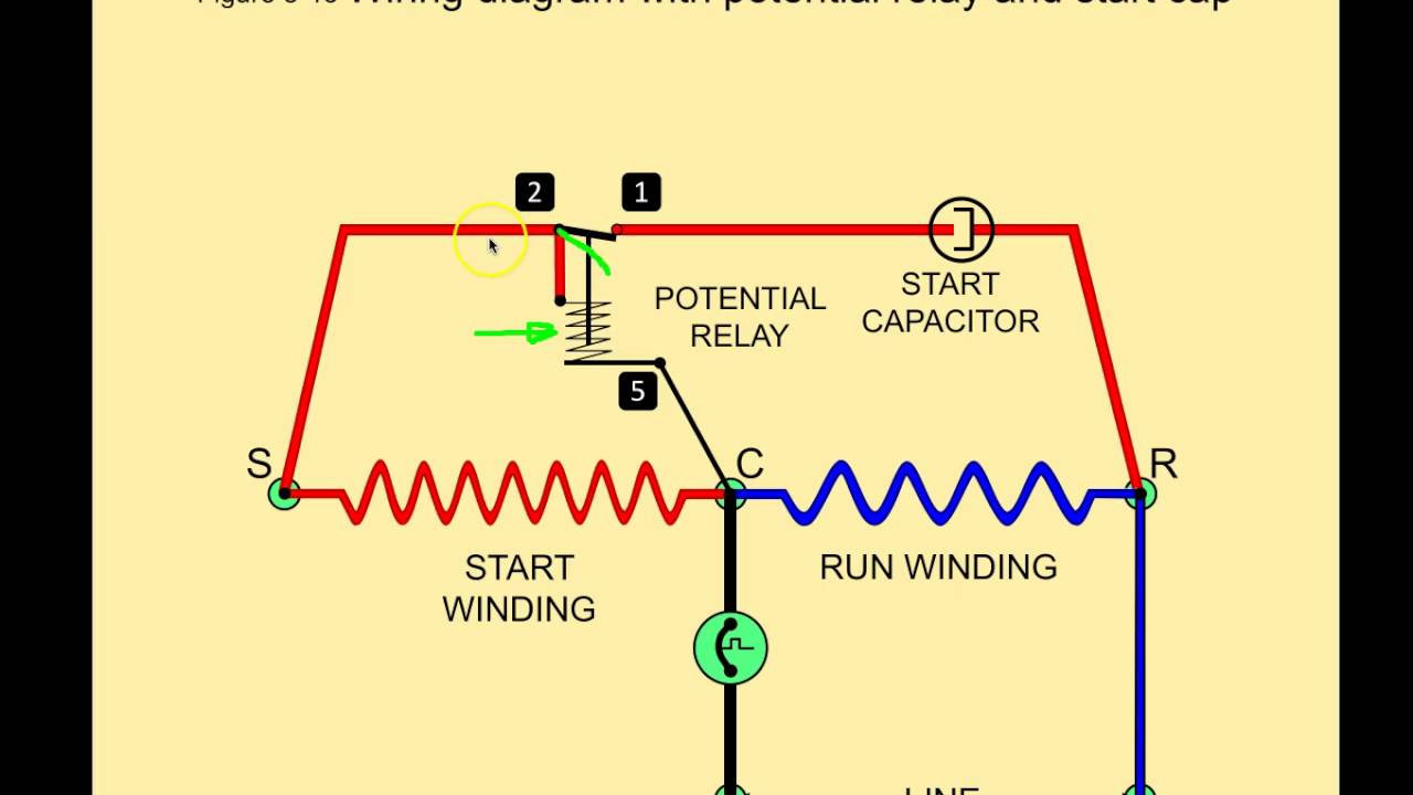
10 3 Potential Relays 10 4 Solid State Starting Relays And

Copeland Potential Relay Wiring Diagram Wiring Diagram
Potential Relays Commercial Refrigeration Youtube

Tf 4415 Refrigerator Capacitor Wiring Diagram Free Diagram
4d81e15 Copeland Potential Relay Wiring Diagram Wiring Library

Explaining the differences between current relays and potential relays and their role in starting compressors.
Copeland current relay wiring. Motors for copeland semi hermetic compressors. A over current thermal protection switch in the terminal box for single phase motors voltage ph hz g 220 230 1 50. 1 ma1a a air conditioner schematic diagram and electric heater wiring options v 1 phase 60 hertz a 5kw 5kw 5kw top 2 banks notes. Current relay cut.
If not the structure won t function as it should be. The reason for this is that the compressor pumps. Diagnosing solving relay problems learn about the successful application of a starting relay including proper installation wiring troubleshooting and replacement of the relay. Potential relay wiring diagram compressor potential relay wiring diagram copeland potential relay wiring diagram mars potential relay wiring diagram every electrical arrangement consists of various distinct components.
Accordance with the position of the capacitors and relay shown on the wiring diagram. R efrigeration and air conditioning technicians know that the hermetic compressor is the heart of the cooling sys tem. In addition electrical service information is provided for copeland condensing. Wholesaler copeland ge p n pick up drop out cont.
Compressor wiring diagrams with motor winding connec fig. Each part should be set and connected with different parts in particular way. Best ideas plan symbol electrical wiring 619 x 672 121 kb jpeg building plan 1212 doc schematic technical info doc schematic parts list schematic logic diagram using nand gate maxo. Cc bc seq ctd control compressor circuit heater option compressor contactor blower control copeland k1 scroll.
P n brand p n volts volts rating potential relay data 940 0001 82 040 0166 39 3arr3t3u5 220 240 40 90 332 60.

Automotive Relay Diagram With Images Relay Circuit Diagram

E2 Motors And Motor Starting Ppt Video Online Download
Http Www Hvacrinfo Com Cope Manuals Electhb Pdf

Air Compressor Capacitor Wiring Diagram Before You Call A Ac

Zd 0985 Wiring Diagram For A Potential Relay Schematic Wiring

Wiring Diagram Bathroom Bar Lighting Diagram Light Switch Wiring

Kdeawtk T7 D7m

17 Basic Car Electric Fuel Pump Wiring Diagram Car Diagram In
623ec8 Compressor Potential Relay Wiring Diagram Wiring Resources

17 Innovative Circuit Diagram Ideas Electrical Circuit Diagram

Wiring A Motor Control Circuit Com Imagens Comandos Eletricos
Https Climate Emerson Com Documents Coresense Diagnostics Module For Copeland Stream Compressors Technical Information En Gb 4267574 Pdf

Lennox G16 Wiring Diagram Wiring Diagram And Schematics With
